If you’ve ever watched a Flux-Cored Arc Welding (FCAW) welder pull a smooth, consistent bead on a ship’s hull, a construction beam, or a heavy agricultural implement, you’re not just seeing good craftsmanship—you’re seeing the payoff of a perfectly calibrated flux-cored wire manufacturing machine. As someone who’s spent the last 18 years building, fine-tuning, and supporting these machines for fabrication shops, welding equipment brands, and large-scale manufacturing facilities, I can tell you this: calibration isn’t a one-and-done checkbox. It’s a repetitive, detail-driven process that turns raw steel strip and granular welding flux into a product that doesn’t just work—it outperforms solid wire, saves welders hours of prep and rework, and keeps production lines moving without costly hiccups. Flux-Cored Wire Manufacturing Machine
Most new buyers I talk to when they source a flux-cored wire machine assume calibration is a simple test run of a few settings. Let me set the record straight: before any wire even touches a spool, our calibration process goes through 12 distinct, sequential steps, each designed to eliminate tiny, almost invisible errors that snowball into big problems later. A poorly calibrated machine doesn’t just make bad wire—it makes wire that burns too hot, splatters everywhere, breaks mid-weld, or has flux gaps that cause porosity that takes hours to grind out. I’ve seen a shop lose $40,000 in a single month reworking parts because their new machine’s calibration was rushed, and I’ve seen a 50-person fabrication line boost their output by 22% within a week of our team’s calibration check. Let me walk you through exactly what happens when we calibrate a flux-cored wire manufacturing machine, and why every step matters.
First, before we even power on the machine, we do what we call a “pre-calibration baseline audit.” This isn’t a quick visual check—we measure every core component that will directly impact wire quality. Let’s start with the steel strip feed system, the first station in the line that pulls cold-rolled steel strip from a large roll. We use a digital laser caliper to check the strip’s thickness across its entire width; even a 0.0005-inch variation here will translate to a 0.001-inch difference in the finished wire’s core, which throws off how much flux it can hold. We also check the alignment of the strip’s feed guides with a precision straightedge: a 0.1-degree misalignment here will cause the strip to curve slightly as it moves through the machine, leading to uneven filling of the flux core. Next, we inspect the hopper that holds the granular flux—we run a 50-pound sample flux through a sieve shaker to confirm particle size consistency, because if flux particles are too fine they’ll leak out of the finished wire, and if they’re too coarse they’ll jam the line mid-production. Finally, we check the sealing and crimping dies at the end of the line: these dies fold the steel strip into a U-shape, fill it with flux, then crimp it shut to seal the core. Even a tiny burr on a die’s edge will scratch the steel strip, leading to micro-cracks that break the wire under tension. This pre-cal step takes 2-3 hours for a standard 20-ton-per-day machine, but skipping it is like baking a cake with a lopsided pan—you might save time upfront, but the end result will fall flat every time.
The next step is calibrating the feed rate control system, which is the heartbeat of the entire line. The feed rate determines how fast the steel strip moves through the crimping and sealing stations, which in turn controls how much flux is drawn into the U-shaped strip and how tightly the wire is crimped. Too fast, and you’ll get gaps in the flux core; too slow, and the flux will clump, leading to inconsistent wire diameter. We use a precision linear encoder, a tool that measures distance with 0.0001-inch accuracy, to test the feed rate at three different settings: low (for small-diameter 0.030-inch wire), medium (0.045-inch wire, the most common for general welding), and high (0.068-inch wire for heavy structural work). For each setting, we run the machine for 10 feet of strip, mark the strip at the inlet of the feed rollers, then measure how far the mark travels in exactly 60 seconds. If the encoder reads a feed rate of 10 feet per minute but the actual measurement is 9.8 feet, we adjust the variable frequency drive (VFD) that controls the feed motor by 0.2%—a tiny tweak that makes a huge difference over thousands of feet of production. We repeat this test three times at each speed to ensure consistency; if any reading varies more than 0.05%, we adjust again. I’ve had shops tell me their line is “running fine” only to find their feed rate is off by 1.5%—that means over a 20-hour production shift, they’re making 250 more pounds of over-filled or under-filled wire than they should, wasting thousands of dollars in flux and steel.
Once the feed rate is locked in, we move to calibrating the crimping dies, the most critical part of the line because this is where the flux core’s uniformity is set. The crimping dies are paired upper and lower dies that fold the steel strip into a U-channel, sized to hold exactly the right amount of flux. If the dies are too far apart, the strip doesn’t form a tight U, so flux spills out during crimping; if they’re too close, the strip compresses so much that it crushes the flux particles, ruining their ability to create a stable weld arc. We start by testing the dies’ gap at the narrowest point, using a feeler gauge that measures to 0.0001-inch accuracy. For a standard 0.045-inch wire, the die gap is set to exactly 0.060 inches—wide enough to let the flux flow smoothly, but narrow enough to crimp the top edge of the steel strip shut without damaging the flux. We then run a 5-foot sample of crimped strip, cut it open lengthwise with a precision slitter, and weigh the flux inside to confirm it’s within 1% of the target weight. If the flux is underweight, we adjust the die gap upward by 0.0005 inches; if it’s overweight, we narrow the gap slightly. We repeat this 10 times until the flux weight is consistent, then mark the die’s adjustment screws so no one working on the line accidentally moves them later. I always tell clients: if you mess up the die gap calibration, you can make 100 miles of wire that’s fine enough for small jobs but terrible for structural welding that needs porosity-free beads—so this step is non-negotiable.
Next comes the sealing die calibration, which is where the crimped U-channel of flux and steel is pressed closed to form a solid wire. This die uses high-pressure rollers that squeeze the two edges of the steel strip together, welding them (or cold-welding, in most modern machines) to seal the flux inside. The pressure here is key: too little pressure, and the seal will leak, leading to flux contamination during welding; too much pressure, and the steel strip will thin excessively, making the wire brittle and prone to breaking when it’s drawn through the final sizing dies. We use a hydraulic pressure gauge calibrated to our in-house reference standard to set the roller pressure, targeting 12,000 psi for 0.045-inch wire. We then run a 10-foot sample of sealed wire, measure its diameter with a laser micrometer to confirm it’s within 0.001 inches of the target. If the diameter is larger than desired, we increase roller pressure; if it’s smaller, we decrease pressure. We also check for seal integrity by submerging a 1-foot length of wire in water, then gently squeezing it to see if any flux particles leak out—any leak means the seal is too weak, so we adjust immediately. Last year, a client asked us to skip this seal test because they wanted to start production early; 3 days later, they had 50,000 pounds of wire leaking flux, which was unusable, costing them $12,000 in material and downtime. That’s why this step isn’t a “checkmark”—it’s a hard stop until it’s perfect.
After sealing, the wire goes through a series of sizing dies to bring it to its final, consistent diameter—this is where we calibrate the drawing system. Sizing dies are made of industrial diamond, so they can handle the high friction of pulling steel through them, but even a 0.0005-inch variation in a die’s bore will make the wire diameter uneven. We start with a rough sizing die, then a medium, then a final finish die. For each die, we use laser micrometry to measure the wire diameter as it exits the die, adjusting the draw motor’s speed and tension to keep the wire pulling evenly. Tension is especially important here: if the wire is pulled too tight, it will stretch, becoming thinner than the target; if pulled too loose, it will have ovality (egg shape) that causes uneven feed in the welding gun, leading to inconsistent bead width. We calibrate tension using a load cell that measures the force required to pull the wire, setting it to 15 pounds for 0.045-inch wire—enough to keep the wire straight through the dies, but not so much that it deforms the steel. We run 50 feet of wire through the sizing stage, taking diameter measurements every 10 feet, and confirm all readings are within ±0.001 inches. Any wire that’s out of spec gets re-routed back to the feed system, not to the spool.
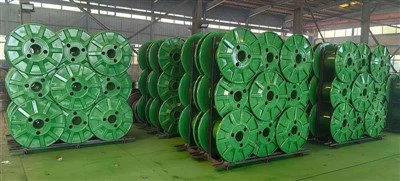
The final calibration step before full production is the tension and spooling calibration, which ensures the finished wire is wound consistently on the spool, no tangles, no overlapping layers. A poorly spooled wire will jam in the welding gun mid-process, leading to stops that take 10 minutes or longer to fix—costing a fabricator hundreds of dollars in downtime per hour. We calibrate the spool’s rotational speed and tension using a rotary encoder, matching the line’s draw speed so the wire is wound at exactly the right rate. We also adjust the spool’s traversing mechanism, the part that moves the wire back and forth as it’s wound, to lay the wire in tight, parallel layers. For a 14-inch spool (the most common size for FCAW welding), we set the traversing distance to 12 inches, leaving 1 inch of space on each side of the spool flange to prevent wire from falling off the edges. We run a full 100-pound spool of wire, then unspool it at 50 feet per minute to test for tangles or uneven winding; if we find even one small tangle, we adjust the traversing mechanism’s alignment by 0.1 degrees. I always tell clients that a well-spooled wire is almost as important as the wire’s core composition—no welder wants to stop mid-weld to untangle a mess of wire off their spool.
Once the machine is calibrated, we don’t just send the client off with a certificate. We do a production trial run, making 500 pounds of wire, then send samples to a third-party welding lab for testing. The lab tests for flux content uniformity, wire tensile strength, porosity resistance, and spatter rate. If all samples meet or exceed industry standards (we benchmark against AWS A5.20, the standard for carbon steel flux-cored electrodes), we do a final walkthrough with the client’s maintenance team, showing them how to perform quick calibration checks on their own—like checking feed rate with a simple stopwatch and measuring wire diameter with a digital caliper. We also provide a calibration schedule: daily pre-production checks, weekly feed rate and die gap checks, and full re-calibration every 6 months, or whenever maintenance is performed on core components.
I know that for many new buyers, calibration sounds like extra work—something that adds to the cost of the machine. But let me be clear: a machine that’s not properly calibrated isn’t just a machine—it’s a liability. It produces wire that costs more per pound to make, that’s more likely to cause rework, that wastes welder time. I’ve heard clients say they saved money by buying a machine from a supplier that “skips calibration” to offer a lower price, only to end up throwing away 20% of their production because of bad wire. The machine I sell is built to last 20+ years, but it only does that when calibrated correctly every single time.
If you’re in the market for a flux-cored wire manufacturing machine, don’t just look at the initial price tag. Ask about the calibration process. Ask how many steps it includes, who performs it, what testing is done after calibration. Because at the end of the day, a great machine is only as good as the care that goes into calibrating it before it ever starts making wire. Whether you’re a small job shop looking to produce custom wire for your own use, or a large manufacturer looking to sell flux-cored wire to third parties, the calibration process is the foundation of consistent, high-quality output. I’ve spent my career refining this process, and I can tell you: when a machine is calibrated right, the wire it makes doesn’t just meet specs—it exceeds them.

If you’re ready to learn more about our calibration process, or to discuss a flux-cored wire manufacturing machine that fits your production needs, don’t hesitate to reach out for a consultation. We can walk you through every step of the process, answer your questions, and even arrange a site visit to see a calibrated machine in action.
Other Auxiliary Equipment References
AWS A5.20/A5.20M: Specification for Carbon Steel Flux-Cored Electrodes for Shielded Metal Arc Welding. American Welding Society, 2022.
Flux-Cored Wire Manufacturing: Process and Quality Control. Industrial Welding Equipment Association, 2021.
Precision Calibration for Welding Equipment. National Institute of Standards and Technology (NIST) Technical Note 1923, 2019.
Three Water Machinery Co., Ltd.
Three Water Machinery Co., Ltd. is one of the most reliable manufacturers and suppliers of flux-cored wire manufacturing machine in China. With abundant experience, we warmly welcome you to buy advanced equipment for sale here and get quotation from our factory. Contact us for more details.
Address: No.15, Jiaye Road, Liuanzhuang Industrial Park, Beichen District, Tianjin, China
E-mail: sales@eqet.com
WebSite: https://www.eqet.com/
